
The pump that boils water at room temperature.
Pressure falls. Vapour forms. Bubbles collapse. Here is the suction-side check behind the reel, with a worked example you can change.
Working in Aspen Plus? Join the Reflux Student trial waitlist →
Join the trial waitlist
Try Reflux Student on Aspen Plus. Use something else? Tell us what to build next. The notes below are free to read.
You’re on the list.
We’ll email you when the build that speaks your software is ready.
Optional, while you wait:
Windows will say it does not recognise the app. Click More info, then Run anyway. The signature is on its way.
Reflux installs on the Windows machine where Aspen Plus runs, so there is nothing to download on this device. We are sending the link to your email. Open it over there.
Not hot. Just low pressure.
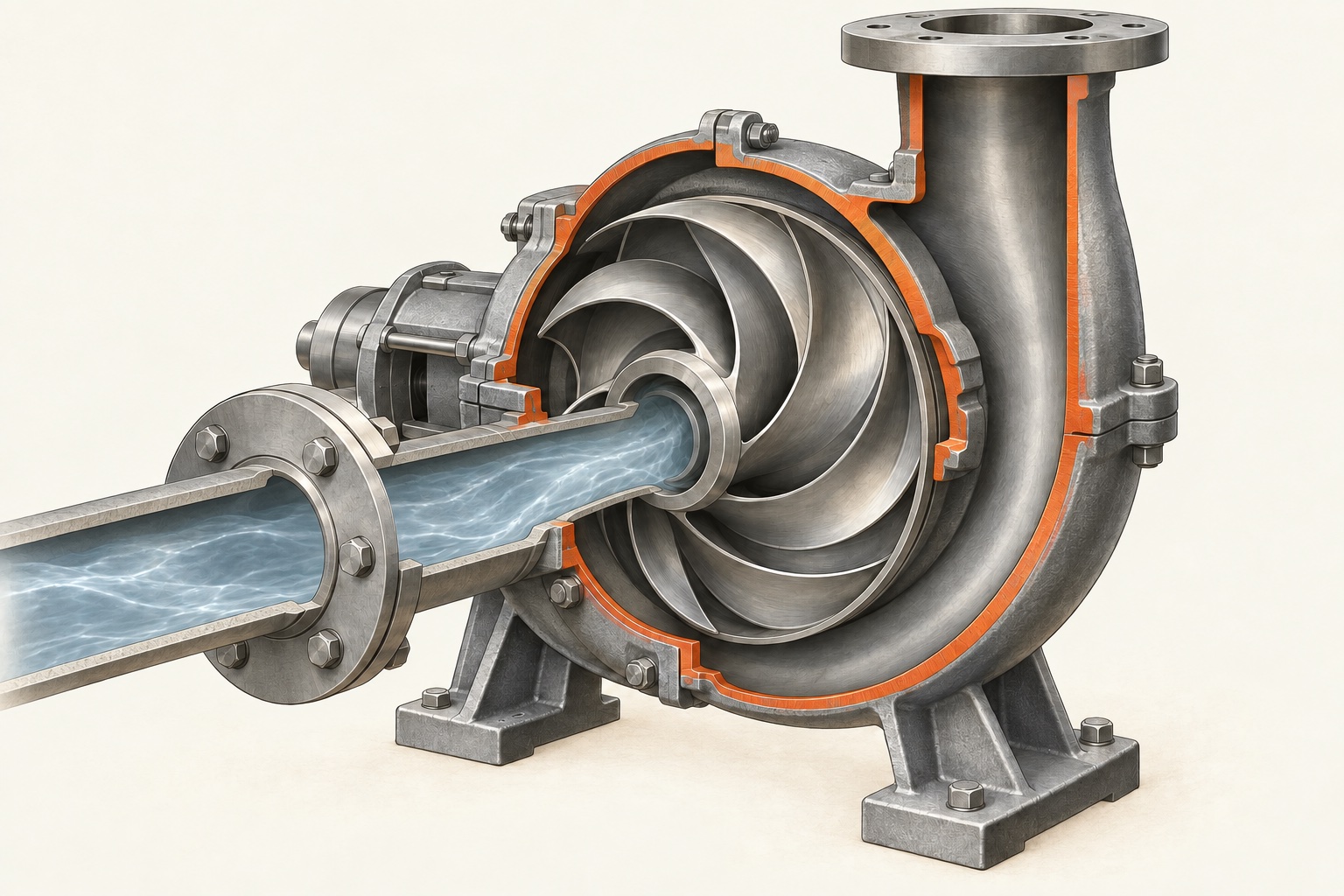
Liquid accelerates into the impeller eye and the local static pressure falls. If it reaches the liquid’s vapour pressure, vapour cavities can form. They collapse when the flow carries them into higher pressure. Repeated collapses near a surface can erode the metal.
For water at 20 °C, vapour pressure is about 2.34 kPa absolute; at 25 °C it is about 3.17 kPa. The reel’s “about 2 kPa” is rounded, and the pressure must be absolute, not gauge. Hotter liquid usually leaves less suction margin.
Sources: NIST water properties; Grundfos, cavitation and its effects on pumps.
“Required” needs a definition.
- NPSHA
- Net positive suction head available: a system property. Total absolute suction head at the impeller datum minus the liquid’s vapour-pressure head.
- NPSH3
- The tested NPSH at a 3% reduction in pump total head due to cavitation, at the specified operating point. It is a performance criterion, not a measured metal-damage threshold.
- NPSHR
- The manufacturer’s required NPSH for specified performance. It may exceed NPSH3. Ask which criterion is on the curve.
A clarification to the reel: NPSHR is not universally the 3% point. Hydraulic Institute’s 2024 guidance uses manufacturer-supplied NPSHR, which must be at least NPSH3. “Already damaged” is too literal: head loss does not establish the extent of erosion. The useful takeaway is that meeting the published requirement alone is not a guarantee of cavitation-free or damage-free operation.
Use the vendor’s margin recommendations and the applicable guidance for your service. The reel’s 0.5–1 m and 20% are illustrative rules of thumb, not interchangeable or universal acceptance limits.
One line from the tank surface.
NPSHA = (psurface,abs − pvapour) / (ρg) + z − hloss
For a large supply tank with negligible surface velocity, steady incompressible single-phase flow to the suction flange, and all inlet losses included. z is the liquid surface elevation above the impeller datum; a suction lift is negative. Use metres of the pumped liquid throughout.
Try the suction-side worksheet
Defaults: illustrative open tank, water near 20 °C. Edit values from your case, in the units shown.
NPSHA10.61 m
NPSHA − NPSHR7.61 m
NPSHA / NPSHR3.54
Exceeds the entered 1.00 m extra margin by 6.61 m.
The entered target is a comparison input, not a recommended design margin. This worksheet does not model cavitation, gas entrainment, transients, inlet recirculation, multicomponent flashing or pump damage.
The default calculation is (101.325 − 2.34) × 1000 / (998.2 × 9.80665) + 2 − 1.5 ≈ 10.61 m. With a vendor NPSHR of 3 m, the available extra head is about 7.61 m. A higher tank level adds NPSHA; more suction losses or a higher vapour pressure removes it.
Check the worst credible suction condition.
- Lowest vessel pressure and liquid level; highest liquid temperature.
- Losses at the actual flow, including strainers, valves and fouling.
- Vendor curves at the actual speed, impeller and fluid conditions.
- Margin over the full operating range, including start-up and transients.
- Absolute and gauge pressure, elevation datum and liquid-head units.
A pump/system-curve intersection answers the operating-flow question. It does not replace this suction check. For the earlier selection reel, see the pump-curve page.
Size the pump. Check the suction side.
Reflux Student works with Aspen Plus on Windows. Join the trial waitlist to try it, or tell us which simulator you want next. We will email you about the build that fits your software.
Join the trial waitlist →Nathan Ruberto · Co‑Founder, CEO
Back to reflux.sh →